

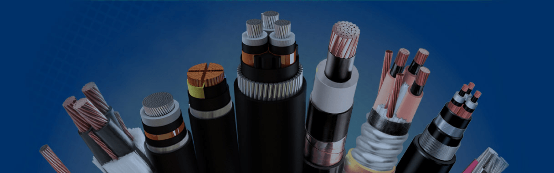
Instrumentation Cable
Instrumentation cables are designed to transmit low-voltage control, monitoring, and measurement signals in industrial automation and process control systems. We offer a broad selection of instrumentation cables designed to support dependable signal transmission between field devices and control systems across industrial sectors including energy, process manufacturing, utilities, and infrastructure.
Their primary purpose is to carry sensitive analog and digital signals while minimizing electromagnetic interference (EMI) and signal loss. This helps ensure accurate data transmission between sensors, transmitters, analyzers, PLCs, DCS systems, and other critical control devices, even in electrically noisy industrial environments.
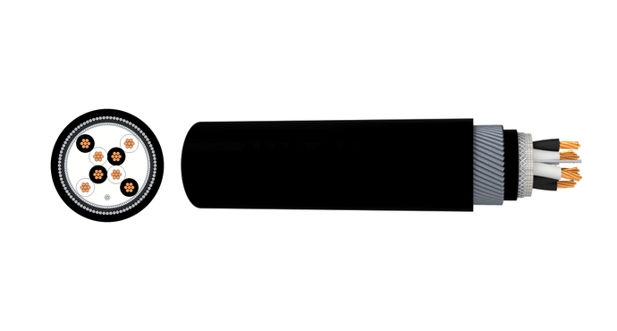
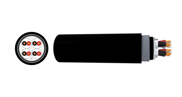
A typical instrumentation cable consists of copper conductors, insulation, twisted pairs or triads, shielding, and an outer sheath. Depending on the application, cables may feature an overall screen or individual and overall screens to improve signal integrity and reduce crosstalk. Common types include Overall Screen Instrument Cable, Individual + Overall Screen Instrument Cable, Armoured Overall Screen Instrument Cable, and Armoured Individual + Overall Screen Instrument Cable.
Both armoured and non-armoured constructions are available to suit different installation requirements. Non-armoured cables are ideal for indoor and protected areas, while armoured cables provide additional resistance to impact, crushing, and environmental exposure, making them suitable for outdoor, direct burial, and heavy-duty industrial installations. Choosing the right shielding and armour configuration helps ensure long-term reliability, stable signal performance, and effective protection in demanding operating conditions.
Instrumentation Cable Standards
Our Instrumentation Cables are manufactured in accordance with internationally recognized standards to ensure reliable signal transmission, electrical performance, and long-term durability in industrial environments. Depending on project requirements, the following standards are commonly applied.
| Standard | Description | Typical Applications |
| BS 5308 | The most widely specified standard for instrumentation cables, covering armoured and unarmoured constructions with overall or individual/overall screening. | Oil & Gas, Petrochemical, Power Generation |
| PAS 5308 | Earlier British specification that remains common in existing plants and replacement projects. | Process Industries, Plant Maintenance |
| EN 50288-7 | European standard for instrumentation and communication cables used in industrial control systems. | Industrial Automation, Manufacturing |
| UL 13 (PLTC) | North American standard for Power-Limited Tray Cables used in instrumentation and control circuits. | Industrial Facilities, Building Automation |
| UL 2250 (ITC) | North American standard for Instrumentation Tray Cables designed for process control applications. | Process Plants, Industrial Automation |
| IEC 60092 | Standard for instrumentation and control cables used in marine and offshore environments. | Offshore Platforms, Marine Vessels |
Instrumentation Cable
Get A Free Quote
Need Help?
Your Trusted Business Partner for Professional Cable Solutions
/ AMG FAQ /
Frequently Asked Questions
| Question | Your answer → cable choice |
| What signal type? | Analog (420mA, TC, RTD) → individual+overall screen Digital (RS485, Modbus) → overall screen may be enough |
| Where will it be installed? | Indoor tray / conduit → nonarmoured Direct burial / outdoor / rodents → armoured |
| How long is the run? | Long distance (>300m) → larger gauge (1618 AWG) Short distance → smaller gauge (2024 AWG) |
| Any hazardous location? | Class I, Div 2 → need MCHL or CIC armoured cable |
| Which standard? | Europe → BS EN 502887 North America → UL 13 PLTC or UL 1277 TC |
Bottom line:
- Sensitive analog + mixed signals → Individual+Overall Screen (armoured or non‑armoured)
- Tough environment → Add armour
- Simple digital / clean environment → Overall screen only
To ensure signal integrity and safety before and after installation, cables undergo several critical field and factory tests:
- Continuity Test: Checks each conductor and drain wire from end to end to ensure there are no broken wires or open circuits.
- Insulation Resistance (IR) Test: Uses a Megohmmeter (Megger) to measure the resistance between conductors and between conductors and screens, ensuring the insulation compound is not degraded or compromised.
- Conductor Resistance Test: Verifies that the copper wire meets standard ohms-per-kilometer ratings according to IEC 60228, ensuring no power drop along long runs.
- High-Voltage (Hypot) Test: Applies a voltage higher than the operating rating for a brief period to check for latent insulation weaknesses.
- Shielding Integrity/Grounding Test: Confirms that the aluminum tape and drain wire are continuous and not accidentally touching the copper conductors or the ground along the run.
Instrumentation cables are defined by 3 key variables. Mix and match them to get the right cable for your job.
- By Shielding (2 types)
Overall screen – one shield around all conductors.
Individual+Overall screen – each pair shielded + an overall shield.
- By Conductor arrangement (3 types)
Single pair / Multiple pairs / Triads (3 conductors twisted)
- By Armouring (2 types)
Non‑armoured – flexible, for trays or indoors.
Armoured – SWA steel wire/tape, for direct burial & mechanical protection.
- By Insulation material (common types)
PVC (general purpose) / XLPE (higher temp) / LSZH (low smoke)
- By Voltage & standard
PLTC (300V), ITC (150V), TC (600V), MC‑HL (hazardous locations)
Our product lineup covers the four essential combinations most industrial applications need.
In one sentence: They protect a low‑level measurement signal from electrical noise and physical damage.
Three core mechanisms:
- Twisted pairs – Each signal and its return are twisted together. Any magnetic interference hits both wires equally and cancels out (common‑mode rejection).
- Shielding – An aluminium foil (or copper braid) wraps the pair(s). It intercepts electric field interference (RFI/EMI) and sends it to ground via the drain wire.
- Drain wire grounding – The drain wire touches the shield and is grounded at one end only (usually at the control system side). This prevents ground loops.
Individual+Overall screen adds extra protection:
- Each pair has its own shield → no crosstalk between pairs.
- An outer shield over everything → blocks external noise.
Rule of thumb: Field repairs are limited to minor surface jacket damage that does NOT reach the shielding or insulation.
| Damage type | Can you fix? | How? |
| Outer jacket scratch / small cut (shield intact) | Yes | Clean area, apply approved jacket repair tape or heatshrink sleeve (watertight if outdoor) |
| Shield cut or exposed | Possibly | Requires professional splice kit with shield continuity restored – not recommended for critical circuits |
| Conductor broken | No | Replace the whole cable segment |
| Insulation compromised | No | Replace – risk of leakage and signal error |
| Water ingress / flooded cable | No | Replace – moisture will cause longterm corrosion and insulation drop |
Practical advice:
- For field‑mount instruments, always leave a service loop so you can re‑terminate instead of splicing.
- If you must splice, use an IP68 junction box and terminal blocks – never twist and tape instrumentation cables.
| Feature | Control Cable | Instrumentation Cable |
| Primary job | Send commands (start/stop, open/close) | Send measurements (420 mA, TC, RTD, Modbus) |
| Typical voltage | 120 V AC, 24 V DC, up to 600 V | 24 V DC, 5 V, mV (thermocouple) |
| Signal strength | Relatively high (mA to several amps) | Very low (µA to 20 mA) |
| Noise tolerance | High – a spike won’t affect command | Very low – noise can change reading |
| Construction | Concentric (all wires together) | Twisted pairs (each pair twisted) |
| Shielding | Optional, often basic foil | Essential – often individual+overall |
| Common standard | UL 1277 Type TC (600 V) | UL 13 PLTC / UL 2250 ITC / BS EN 502887 |
Simple memory aid:
Control cable = muscle (carries action commands)
Instrument cable = nerve (carries sensory data)
Typical range: 16 AWG to 24 AWG (stranded copper)
| AWG | mm² (approx) | Best use case |
| 16 AWG | 1.5 mm² | Very long runs (>800m), high vibration areas |
| 18 AWG | 1.0 mm² | Long industrial runs (300800m), general process |
| 20 AWG | 0.5 mm² | Standard panel to field (most common) |
| 22 AWG | 0.34 mm² | Short runs, highdensity cabinets |
| 24 AWG | 0.25 mm² | Very short, spacelimited (e.g., inside junction boxes) |
All instrumentation cables use stranded conductors – never solid. Flexibility and vibration resistance are achieved through stranding, in accordance with IEC 60228 Class 2 or Class 5.
For large-scale commercial or industrial projects, bulk instrumentation cable should be sourced through certified B2B channels to guarantee strict quality compliance:
- Direct from Manufacturers like AMG Cable: Partnering directly with a specialized cable factory like AMG Cable offers maximum cost efficiency, custom surface printing, tailored core counts, and exact production lengths wound on heavy-duty wooden drums. We engineer fully compliant solutions (BS 5308, EN 50288-7, UL) tailored precisely to your project’s engineering blueprints.
- Global Industrial Distributors: Supply chain organizations like Anixter, Rexel, or local authorized electrical wholesalers are ideal if you need standard specifications shipped immediately from regional, off-the-shelf stock.
- Note for Procurement: Always ensure your bulk supplier provides comprehensive Material Test Reports (MTRs) and factory compliance certificates (such as CE, RoHS, UL, or ISO). If you are shipping overseas, choosing a partner like AMG Cable ensures access to specialized seawater-resistant or UV-protected packaging, preserving your material’s integrity from the cargo container to the job site.
Yes, instrumentation cables are highly recommended and widely used for interconnecting purposes within industrial control systems. They are perfectly suited for wiring the internal connections between marshalling cabinets, terminal block racks, relay panels, and PLC/DCS input/output (I/O) modules. Because control cabinets can become densely packed with various wire types, using shielded instrumentation cables for these tight internal interconnects ensures that adjacent power supplies or relays do not introduce electromagnetic noise into the system’s sensitive data streams.
Soldering industrial instrumentation cables requires precision to maintain signal integrity and shielding continuity. Follow these essential steps for a professional B2B termination:
- Initial Cable Prep: Gently score and peel away the external sheath, taking absolute care to avoid slicing into or damaging the underlying insulated conductors. Separate the twisted pairs, aluminum foil shield, and the tinned copper drain wire.
- Tinning: Strip 3–5 mm of insulation from the individual conductors. Apply a thin layer of high-quality electronic solder to both the exposed copper strands and the connector pins. Tinning ensures a rapid, reliable thermal bond.
- Soldering Cores: Join the tinned wire to the connector terminal using a clean soldering iron. Maintain steady contact until the solder flows smoothly into a shiny joint.
- Shielding Continuity: Crucially, solder the tinned copper drain wire to the connector’s designated ground pin or metallic shell. This step is vital to preserve the electrostatic shield’s ground path and block electromagnetic interference (EMI).
- Insulation: Slide pre-placed heat-shrink tubing over the finished joints and apply heat to seal the connections against moisture and short circuits.

Have Questions?
Get in Touch with Us.
AMG Cable Group support 24*7 service and technical assistance.
Phone /Whatsapp / Wechat
+86 188 3803 6118Address
High-Tech Industrial Development Zone,Zhengzhou City,Henan Province,ChinaSend Us a Message
Please feel free to leave a message. We will reply in 24 hours.
/ AMG WIRE&CABLE /
Your trusted partner in high- performance wire and cables
Our team stands by 24/7, responding promptly to
inquiries and providing most quotations within 24 hours.