

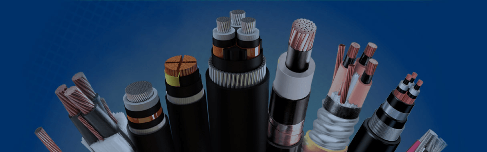
ESP Cable
ESP Cable, also known as Electric Submersible Pump Cable or Submersible Oil Pump Cable, is a specialized power cable designed to deliver continuous electrical power to downhole ESP systems used in oil, gas, geothermal, and deep well applications. Installed alongside the production tubing and operating thousands of meters below the surface, ESP cables play a critical role in maintaining stable pump performance and uninterrupted oil production in some of the world’s harshest environments.
In an ESP system, cable reliability is not just a component issue — it directly affects the productivity and operating cost of the entire well. Industry experience shows that cable failure is one of the leading causes of ESP system shutdowns. In offshore and deepwater operations, a single workover intervention can cost hundreds of thousands or even millions of dollars. For this reason, selecting the right ESP cable structure, insulation system, and protective materials is essential for improving production efficiency, reducing downtime, and lowering total lifecycle costs.
ESP cables are engineered to operate under extreme downhole conditions where ordinary power cables cannot survive. These environments typically involve high temperatures, high pressure, continuous immersion, corrosive gases, oil exposure, chemical attack, and severe mechanical stress during installation and operation. Depending on the well condition, cable designs may include advanced insulation compounds, gas barriers, corrosion-resistant armor, and high-temperature materials to ensure long-term reliability.
Downhole temperatures commonly range from 90°C to 232°C or even higher in geothermal and high-output wells. At the same time, high-pressure environments containing gases such as H₂S and CO₂ can create serious decompression risks. When pressure changes rapidly, gas may penetrate the cable structure and cause decompression rupture, leading to insulation damage and premature cable failure. In addition, during running and retrieval operations, the cable is constantly exposed to friction, vibration, crushing, and mechanical impact against the casing and tubing.
To withstand these demanding conditions, modern ESP cables are designed with carefully selected conductor materials, high-performance insulation systems, protective jackets, metal armor, and gas-blocking barriers. A properly engineered ESP cable helps ensure stable power transmission, longer service life, improved pump reliability, and safer well operation in both onshore and offshore applications.
Key Cable Design Features & Material Engineering
| Layer | Function | Material Options | Selection Notes |
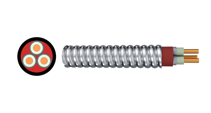
| Conductor | Transmit three-phase power | Oxygen-free copper (bare or tin-plated); solid, stranded, compacted stranded | Solid conductor blocks gas migration; tin plating required with PP insulation |
| Insulation | Provide dielectric separation | EPDM (to 232 °C); PP (to 96 °C); EPR; composite polyimide/EPDM (to 260 °C) | EPDM is the field standard for most wells; PP suits cooler, shallow wells |
| Barrier | Block gas and fluid ingress | Extruded lead sheath; fluoropolymer (PFA/FEP) | Lead is the definitive solution for high H₂S/CO₂ wells; fluoropolymer is a lighter alternative |
| Jacket | Protect against oil, chemicals, and abrasion | NBR (oil-resistant, to 140 °C); EPDM (high-temp, low oil); CSP | NBR is the standard choice in crude oil and brine; use EPDM only when oil exposure is minimal |
| Bedding / Filler (round cables) | Fill interstices, provide cushioning under armor | EPDM or NBR strips; semi-conductive tapes | Ensures a smooth round profile and uniform armor load distribution |
| Armor | Mechanical shield against impact, abrasion, and tension | Galvanized steel (sweet wells); stainless steel 304/316 (moderate H₂S/CO₂); Monel alloy (sour service) | Corrosion resistance must match the well environment to prevent armor failure before electrical degradation |
ESP Cable
Get A Free Quote
Need Help?
Your Trusted Business Partner for Professional Cable Solutions
/ AMG FAQ /
Frequently Asked Questions
An ESP (Electrical Submersible Pump) cable, also referred to as a Submersible Oil Pump Cable, is a specialized heavy-duty power cable used to transmit high-voltage electrical current from surface control equipment down to the submersible pump motor in oil and gas wells. Because it operates under continuous immersion in harsh wellbore fluids, it serves as the critical electrical lifeline that powers artificial lift operations and sustains daily oil production.
Start by defining four things about your well: maximum bottomhole temperature, annular space between tubing and casing, presence of corrosive gases (especially H₂S and CO₂), and motor voltage and current requirements.
From there, the selection follows a logical sequence:
Choose insulation type based on temperature (EPDM for most wells up to 232 °C, PP only for cooler wells below 96 °C).
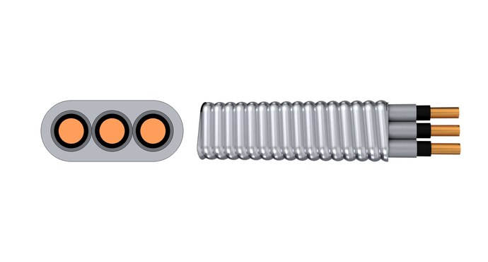
Decide between flat or round cable based on available annular clearance.
Select armor material to match the corrosive environment: galvanized steel for sweet wells, stainless steel or Monel for sour service.
Add a lead sheath barrier if gas permeation and decompression rupture are a risk.
Verify conductor size can carry the motor current over the full cable length without exceeding voltage drop limits.
When in doubt, always give the cable a temperature safety margin of at least 20–30 °C above your maximum expected well temperature. This single decision does more to extend cable life than almost anything else.
ESP cable connections generally fall into three categories: field splices between main cable sections, the connection at the wellhead penetrator, and—most critically—the motor lead connection at the pothead.
Field splices require stripping back each layer carefully, joining conductors with crimped connectors, and then rebuilding the insulation, jacket, and armor layer by layer using tapes, boots, or heat-shrink systems matched to the cable materials. Every splice must be tested for electrical integrity before it goes into the hole.
The motor lead connection (pothead) is the most sensitive joint in the system. It must seal against well pressure while maintaining electrical continuity at the motor terminals. Most operators prefer factory-terminated motor lead extensions because they are assembled and tested under controlled conditions, which reduces the risk of a premature downhole failure.
Testing happens at multiple stages: on the reel after manufacturing, after splicing, during installation, and periodically in operation.
The most common tests include:
Insulation resistance (IR) test – measures the resistance between each conductor and ground, typically using a megohmmeter at 500 V or 1000 V. A sharp drop from baseline readings often signals moisture ingress or insulation damage.
High-potential (hipot) test – applies a DC voltage well above the cable’s rated voltage (typically 1.7 to 2 times rated voltage plus some offset) to verify dielectric strength. This is the definitive go/no-go test before running in hole.
Continuity and resistance checks – confirm conductors are unbroken and phase-to-phase resistance is balanced.
Motor lead seal and pressure test – specific to the pothead assembly, to verify the mechanical seal will hold under well pressure.
A good testing practice is to record baseline values on the drum before shipping, then compare readings at every major step—after transport, after splicing, and during run-in-hole. Trending the IR value over time is often more revealing than a single number.
There is no single price because ESP cable is an engineered product built to order. Cost depends on conductor size, insulation type (PP versus EPDM), whether a lead sheath is included, armor material (galvanized steel versus Monel), and total length. A basic flat cable for a shallow, sweet well will be substantially less expensive than a round, lead-sheathed, stainless-steel-armored cable for a deep HPHT offshore well.
For accurate pricing, you need to specify the well parameters and required cable construction. Manufacturers then quote on a per-meter or per-foot basis. We can provide a budget estimate quickly once you share your well data and required voltage and temperature ratings.
The overwhelming majority of ESP cable failures happen at the motor lead connection—the pothead—and in the first few meters of cable directly above the pump. This area sees the highest temperatures, the most vibration from the pump, and the greatest mechanical stress during installation and pulling. A small insulation nick or a compromised seal at the pothead can lead to a short circuit after only days or weeks in operation.
The second most common failure zone is anywhere the cable passes through a tubing collar or casing restriction, where mechanical damage from rubbing or pinching occurs. That’s why cable protectors and careful run-in procedures are so important.
In terms of failure mode rather than location, decompression rupture caused by gas permeation is one of the most destructive and hardest-to-detect problems. A cable can look perfect when pulled from the well, but internal insulation layers are torn apart by expanding gas—a strong argument for a lead sheath or other gas barrier in any well with significant H₂S or CO₂ content.

Have Questions?
Get in Touch with Us.
AMG Cable Group support 24*7 service and technical assistance.
Phone /Whatsapp / Wechat
+86 188 3803 6118Address
High-Tech Industrial Development Zone,Zhengzhou City,Henan Province,ChinaSend Us a Message
Please feel free to leave a message. We will reply in 24 hours.
/ AMG WIRE&CABLE /
Your trusted partner in high- performance wire and cables
Our team stands by 24/7, responding promptly to
inquiries and providing most quotations within 24 hours.