

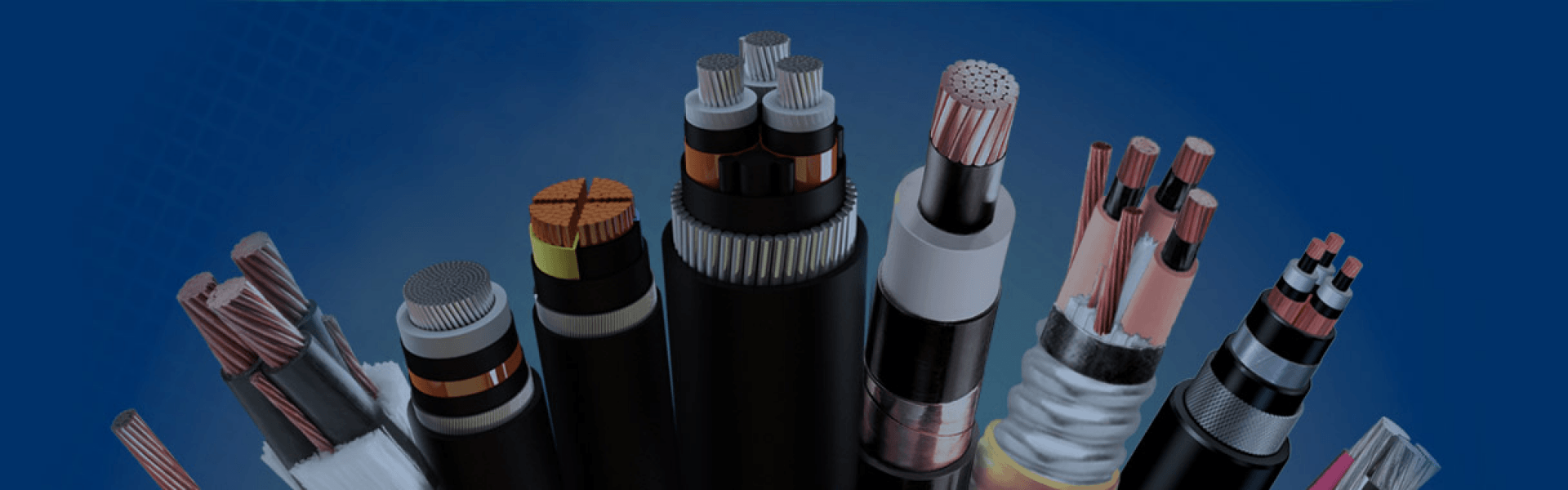
High Voltage Cable
High voltage cable is designed for the transmission and distribution of large amounts of electrical power over medium and long distances. Common voltage ranges typically cover 66kV to 500kV, making these cables suitable for utility transmission networks, substations, renewable energy projects, underground grids, and industrial power systems where stable and efficient power delivery is required. Single-core and three-core XLPE insulated cables are widely used because of their excellent electrical performance, thermal resistance, and long service life.
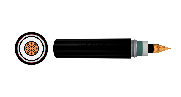
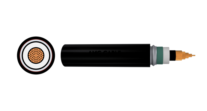
A typical high voltage cable consists of several important layers that work together to ensure safe and reliable operation. The conductor, usually made of copper or aluminum, carries the electrical current. Copper provides higher conductivity and mechanical strength, while aluminum offers a lighter and more economical solution for long-distance transmission. The conductor screen and insulation screen help control electrical stress and maintain a stable electric field inside the cable system. XLPE insulation provides strong dielectric performance under high operating voltages, while metallic shielding improves grounding and electromagnetic protection.
For demanding installation environments, high voltage cables may also include water blocking layers, armor protection, and durable outer sheaths to resist moisture, mechanical impact, chemicals, UV exposure, and environmental aging. These cable systems offer important advantages such as efficient long-distance transmission, lower power losses, high current carrying capacity, stable grid operation, and high reliability. They are especially suitable for underground transmission projects where safety, space efficiency, and long-term performance are critical.
|
Layer
|
Typical Material
|
What It Does
|
|
Conductor screen
|
Extruded semi-conductive compound
|
Smooths the electric field where the conductor strands meet the insulation, preventing local stress concentrations that could cause partial discharge
|
|
Insulation
|
Dry-cured XLPE (cross-linked polyethylene)
|
The primary dielectric — withstands the voltage stress between the live conductor and ground, while maintaining thermal stability up to 90°C under normal load
|
|
Insulation screen
|
Extruded semi-conductive compound, firmly bonded to the insulation
|
Mirrors the conductor screen, keeping the electric field uniform on the outer surface of the insulation and providing a safe interface to the metallic screen
|
|
Waterblocking (swelling tapes)
|
Semi-conductive swelling tape or powder
|
Blocks longitudinal moisture migration between the insulation screen and the metallic screen; the material swells on contact with water, sealing the path and protecting the insulation
|
|
Metallic screen
|
Copper wires with an optional copper tape overlay
|
Carries capacitive charging current and fault current to ground, provides a reference earth plane, and contributes to radial moisture sealing when combined with waterblocking elements
|
|
Waterblocking (swelling tapes or compound)
|
Swelling tape or water-blocking compound
|
Additional protection against longitudinal water ingress; commonly placed under and over the metallic sheath or armor to isolate any external moisture that penetrates the outer layers
|
|
Moisture barrier (radial foil, where specified)
|
Laminated aluminium foil bonded to the outer sheath, or thin metallic tape applied longitudinally
|
Forms a continuous radial vapour and moisture seal — often used when a full metallic sheath is not required but extra humidity protection is needed, such as in ducted or direct-buried installations with moderate moisture risk
|
|
Outer sheath
|
PE (polyethylene) or halogen-free, UV-stabilized compound
|
Protects the whole cable against mechanical abrasion, chemicals, UV radiation, and moisture during handling, installation, and service
|
| Standard | Voltage Range | What It Covers | Why It Matters |
| IEC 60840 | 30 kV – 150 kV | Design, type testing, routine testing and partial discharge limits for XLPE-insulated cables and accessories | The international benchmark for 38/66 kV to 87/150 kV cables. A type-test certificate proves the cable can survive decades of thermal and voltage cycling. |
| IEC 62067 | 150 kV – 500 kV | Stricter tests for extra-high-voltage cables: higher impulses, longer voltage endurance, tighter partial-discharge limits | Covers 127/220 kV and 290/500 kV products. Qualification confirms the insulation handles extreme dielectric stress without slow-developing defects. |
| BS EN 60840 | 30 kV – 150 kV | UK adoption of IEC 60840; identical technical content | Required for UK utility approval. Same technical assurance as IEC 60840, but with recognised UK documentation. |
| BS 7912 | 66 kV – 132 kV | UK-specific standard for XLPE, metallic-sheathed single-core cables; adds water-blocking and mechanical requirements for the British grid | Ensures the cable matches UK distribution network operator preferences for longitudinal water tightness and sheath integrity. |
| VDE 0276 | Up to 500 kV | German standard harmonised with IEC, plus extra sheath abrasion and jacket integrity tests | Demanded in central European transmission projects; the extra mechanical testing adds margin for rocky ground and long pulls. |
| ICEA S-108-720 | 46 kV – 345 kV (and 500 kV) | North American standard for extruded-insulation single-conductor cables; impulse levels and test durations differ from IEC | The reference for US, Canadian, and ANSI-following markets. Using an ICEA-qualified design avoids reengineering to North American surge assumptions. |
| AEIC CS9 | 46 kV – 345 kV (and higher) | User-level specification building on ICEA S-108-720 with tougher long-term ageing tests, lower partial-discharge limits, and stricter quality assurance | When a utility or developer asks for AEIC CS9, they want an extra layer of proven reliability beyond the base industry standard. |
High Voltage Cable
Get A Free Quote
Need Help?
Your Trusted Business Partner for Professional Cable Solutions
/ AMG FAQ /
Frequently Asked Questions
Testing happens in three stages: routine tests at the factory on every metre of cable, type tests to qualify a new cable design, and on-site commissioning tests after installation. The most important routine test is partial discharge (PD) testing — the cable is energised to 1.5 times U₀ or more while sensitive detectors pick up any internal electrical discharges. A clean cable will normally show less than 5 picocoulombs. Other routine tests include a high-voltage AC withstand test, conductor resistance measurement, and a sheath integrity spark test. Once the cable is installed, a soak test at elevated AC voltage or a very low-frequency (VLF) test confirms the whole circuit is sound before it is put into service. For the outer sheath, a DC voltage test between the metallic screen and earth checks for installation damage. Every test is designed to catch defects early — before they become a service outage.
Connecting two lengths of HV cables requires a specialized Straight-Through Joint (or Splice). It must be performed by certified HV jointers because the cable’s layered structure must be perfectly replicated:
1.Preparation: The outer sheath, armor, water-blocking layers, and insulation screens are stripped back step-by-step using high-precision tools according to strict dimensions.
2.Conductor Joining: The copper or aluminum conductors are connected using mechanical shear-bolt connectors or compression crimps to ensure low electrical resistance.
3.Stress Control: A specialized stress-control sleeve or molded rubber block is positioned over the joint area to smoothly manage and redistribute the concentrated electrical field lines.
4.Insulation Restoring: Cold-shrink or heat-shrink joint bodies (often EPDM rubber) are applied to replace the bulk insulation layer.
5.Shielding & Sealing: The metallic screen and armor are structurally reconnected across the joint, and the entire assembly is enclosed in a waterproof, resin-filled, or heavy-duty outer sleeve to block moisture.
Terminating an HV cable involves preparing its end so it can safely connect to overhead lines, transformers, switchgear, or GIS (Gas Insulated Switchgear) installations:
1.Stripping: The cable layers are carefully peeled back to expose the conductor while leaving a precise length of the insulation and semiconducting screen intact.
2.Electric Field Management: A stress cone (built into a heat-shrink or cold-shrink termination kit) is installed at the exact point where the semiconducting screen ends. This prevents localized electrical stress from puncturing the air or insulation.
3.Lug Installation: A crimp or shear-bolt lug is fixed onto the exposed conductor tip for the final bolt-on connection.
4.Environmental Sealing: Anti-tracking, weather-resistant tubes with sheds (skirts) are shrunk over the core to prevent “creeping” currents along the surface and to repel rainwater, salt, and industrial pollution.
An HV cable contains two semiconductor layers—the Conductor Screen (inner) and the Insulation Screen (outer). Their purpose is to equalize the electrical field and eliminate localized electrical stress:
- The Conductor Screen: Stranded metal conductors have a bumpy, uneven surface. If XLPE insulation sat directly on the strands, air gaps would form, causing severe electrical stress concentrations and immediate insulation breakdown. The inner semiconductor fills these gaps, creating a perfectly smooth, cylindrical conductive surface around the metal core.
- The Insulation Screen: Placed between the XLPE insulation and the metallic shield, it ensures that the electrical stress lines remain perfectly radial, uniform, and contained entirely within the main insulation layer, preventing localized arc tracking.
Yes, you can install high-voltage cables on cable trays, but it is subject to strict engineering regulations and local electrical codes (such as NEC or IEC guidelines):
- Tray Specification: Trays must be industrial-grade, heavy-duty (typically ladder-type trays to allow maximum heat dissipation), and constructed from heavy-gauge galvanized steel, aluminum, or FRP.
- Spacing and Derating: HV cables generate significant heat. They must usually be laid in a single layer with a minimum clear clearance between cables (often equal to one cable diameter) to prevent overheating. The cable’s current-carrying capacity must be structurally derated based on the layout.
- Securing and Cleating: Cables must be secured with heavy-duty, non-magnetic HV cable cleating systems capable of withstanding the massive electromagnetic pulling forces generated during a short-circuit fault.
- Safety & Grounding: The tray system must be continuously and robustly grounded, and labeled with high-visibility warning signs to prevent unauthorized access.
High voltage cables carry large amounts of electrical power from generation sources to major load centres. Their key applications include backbone transmission networks (overhead-to-underground transitions, long-distance onshore and submarine links), grid interconnections between substations, connection of renewable energy plants such as offshore wind farms and large solar parks, power station export circuits for hydro, thermal, and nuclear plants, industrial supply to large factories and refineries, and urban underground distribution where overhead lines are not practical. In every case, the role is the same: transfer high power at high voltage with minimal losses and high reliability.
Selection starts with a few non-negotiable parameters, then moves into detailed engineering validation.
1.Define the system voltage and earthing. This sets the required U₀/U rating (e.g. 38/66 kV, 64/110 kV) and immediately narrows the product range.
2.Determine the current rating you need. Calculate the continuous load, then factor in installation conditions — soil thermal resistivity, burial depth, ambient air temperature, and grouping with other circuits. This gives the minimum conductor cross-section.
3.Check short-circuit withstand. The conductor and the metallic screen must carry the prospective fault current for the circuit protection clearing time without exceeding their temperature limits.
4.Choose the insulation and sheath construction. For most projects this will be XLPE with a metallic sheath (corrugated aluminium or lead alloy) for radial moisture sealing, or a copper wire screen with a PE jacket for lighter-duty environments. Consider additional armour if mechanical protection is needed.
5.Match the applicable standard. Whether it is IEC 60840, ICEA S-108-720, BS 7912, or another, the standard determines the test levels and quality baseline. Match it to the project specification.
6.Validate the voltage drop and power losses over the route length, especially for long circuits where these can become the limiting factor rather than ampacity alone.
7.Consider the installation method and accessories. Check bending radius, pulling tension, and whether the joints and terminations needed for the route are available and proven with the cable design.
Once these steps are completed, you will have a specific cable cross-section, voltage rating, and construction type that fits the electrical, mechanical, and regulatory requirements of the project. In practice, the cable manufacturer will support you with the detailed ampacity and short-circuit calculations once the basic voltage rating and route conditions are known.

Have Questions?
Get in Touch with Us.
AMG Cable Group support 24*7 service and technical assistance.
Phone /Whatsapp / Wechat
+86 188 3803 6118Address
High-Tech Industrial Development Zone,Zhengzhou City,Henan Province,ChinaSend Us a Message
Please feel free to leave a message. We will reply in 24 hours.
/ AMG WIRE&CABLE /
Your trusted partner in high- performance wire and cables
Our team stands by 24/7, responding promptly to
inquiries and providing most quotations within 24 hours.