

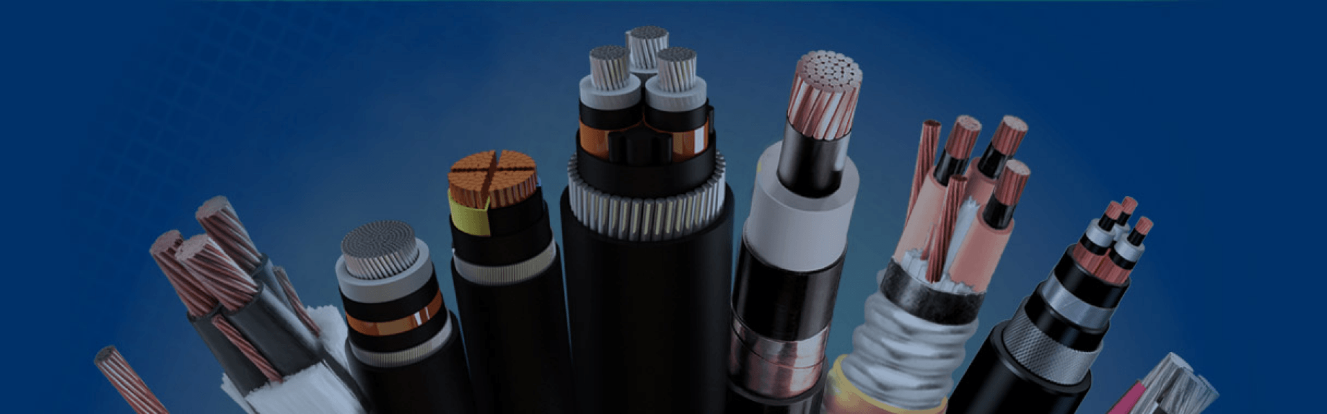
IEC 60502-2 Cable
IEC 60502-2 is an international standard published by the International Electrotechnical Commission (IEC) for extruded insulated medium voltage power cables and their accessories. It mainly applies to fixed installation power cables with rated voltages from 6 kV up to 30 kV, widely used in utility power distribution systems, substations, industrial plants, renewable energy projects, infrastructure construction, and underground transmission networks. These cables are designed for reliable medium voltage power transmission under demanding electrical and environmental operating conditions.
The standard does not cover special applications such as overhead systems, mining cables, submarine cables, shipboard cables, or nuclear facility cables. It focuses on fixed-installation medium voltage power distribution.
Our IEC 60502-2 cables are manufactured according to the latest edition: IEC 60502-2:2014 + AMD1:2024 CSV. IEC 60502-2 clearly defines medium voltage cable ratings using the expression U₀/U (Uₘ). U₀ represents the rated power-frequency voltage between conductor and earth or metallic screen, U represents the rated voltage between conductors, and Uₘ indicates the maximum system voltage that the equipment may withstand during operation. Standard voltage classes commonly include 3.6/6 (7.2) kV, 6/10 (12) kV, 8.7/15 (17.5) kV, 12/20 (24) kV, and 18/30 (36) kV, covering most medium voltage distribution applications in industrial and utility systems.
IEC 60502-2 cables use copper or aluminum conductors with XLPE or EPR insulation systems. XLPE is widely used due to its high dielectric strength, low dielectric loss, thermal stability, and 90°C continuous operating temperature. Sheath materials such as PVC, PE, or LSZH are selected based on installation conditions, offering protection against moisture, UV, chemicals, and fire risk.
The standard also specifies strict routine, sample, and type testing requirements, including partial discharge testing, voltage testing, insulation thickness verification, thermal performance testing, and aging resistance evaluation to ensure long-term operational reliability in medium voltage power systems.
IEC 60502-2 medium voltage cables are widely recognized for their stable electrical performance and long operational reliability. Typical technical characteristics include high dielectric strength, low insulation loss, high operating temperature capability, strong moisture resistance, chemical resistance, UV resistance, optional flame retardant and LSZH designs, as well as excellent long-term aging performance for demanding industrial and utility environments.
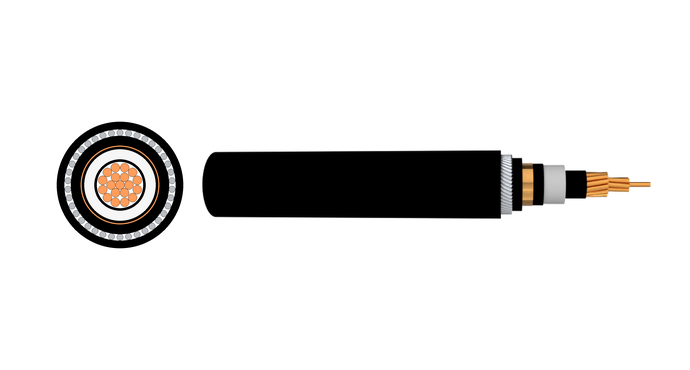
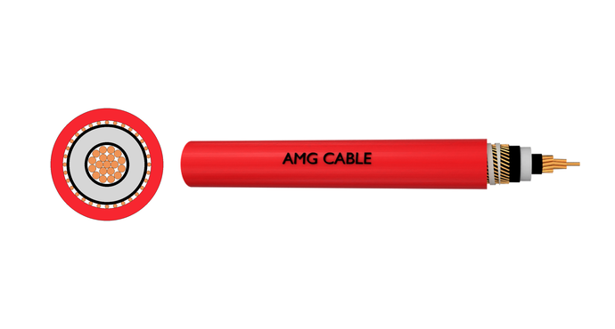
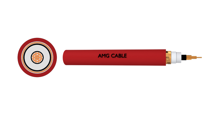
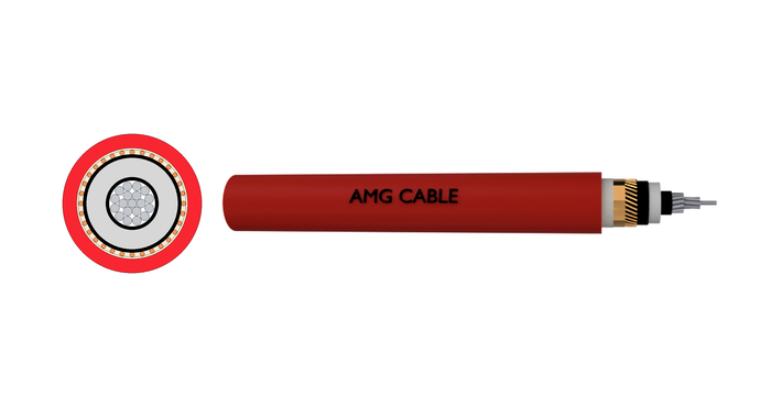
| Cable Layer | IEC 60502-2 Technical Mandates & Design Rules | Permitted Materials | Temperature Thresholds & Limits |
| Conductor | Complies with IEC 60228 (Class 1/2). MV stranded requires circular compacting to eliminate voltage spikes. Size: 1.5–1600 mm². | Annealed Cu (plain/coated), Plain Al, or Al Alloy. | Matches insulation rating. |
| Conductor Screen | Mandatory extruded layer to uniformize the electric field and eliminate stress spikes from strands. | Extruded semi-conducting compound. | Matches or exceeds insulation limits. |
| Insulation | Mandatory triple co-extrusion to prevent micro-voids. Thickness scales with voltage. PVC prohibited above 3.6/6 kV due to high dielectric loss. | XLPE, EPR, or PVC (permitted for baseline 3.6/6 kV only). | XLPE/EPR: 90°C continuous / 250°C short-circuit. PVC: 70°C continuous / 160°C short-circuit. |
| Insulation Screen | Extruded layer for radial field grounding. Available as Strippable (peelable) or Bonded (requires scraping tools). | Extruded semi-conducting compound. | Stable up to 250°C. |
| Metallic Screen | Mandatory grounding element to safely carry earth-fault currents. Cross-section sized per substation fault calculations. | Helical Copper Wires + tape (CWS) or overlapped Copper Tapes (CTS). | Bound by tape and sheath limits. |
| Armour Layer (Optional) | Provides mechanical protection for direct burial/pulling. Single-core must be non-magnetic to prevent inductive loop heating. | Single-Core: AWA or ATA. Multi-Core: SWA or STA. | No restriction on core limits. |
| Outer Sheath | Protects against moisture, chemicals, and abrasion. Minimum thickness calculated via standard core-diameter formulas. | PVC (ST1/ST2: flame retardant), PE (ST7: moisture barrier for burial), or LSZH. | PVC: 80°C to 90°C. PE: Down to -40°C. |
| Selection Parameter | Core Technical Criteria & IEC 60502-2 Mandates | Practical Engineering & Application Recommendation |
| Rated Voltage (U0/U) | Matches system line-to-earth (U0) and line-to-line (U). Standard ratings: 3.6/6 kV up to 18/30 kV. | Specify based on maximum system voltage (Um) to handle grid fluctuations and overvoltage. |
| Conductor Material | Cu or Al (IEC 60228, Class 1/2). Stranded MV conductors must be circular compacted to avoid electrical stress. | Copper for tight substation spaces and high loads. Aluminum for long runs to reduce cost and weight. |
| Insulation Type | XLPE or EPR. PVC is strictly prohibited above 3.6/6 kV due to high dielectric losses. | XLPE for standard high efficiency (90°C load / 250°C short-circuit). EPR for high flexibility and damp areas. |
| Insulation Screening | Extruded semi-conducting compound over core. Specified as Bonded (fused) or Strippable (peelable). | Strippable for fast, clean splicing and terminating. Bonded for high-stress or heavy industrial setups. |
| Metallic Screen Design | Copper Wire (CWS) or Copper Tape (CTS). Cross-section must be sized for system earth-fault currents. | CTS for standard networks with normal fault risks. CWS for high short-circuit capacity or EMI shielding. |
| Armour Configuration | Mechanical protection. Single-core must be non-magnetic to prevent inductive loop heating. | [Unarmoured]: Best for ducts or indoor trays. [Single-Core]: Use AWA or ATA to prevent eddy currents. [Multi-Core]: Use SWA or STA for direct burial. |
| Outer Sheath Compound | Protects against moisture, chemicals, and abrasion. Types include PVC (ST1/ST2), PE (ST7), and LSZH. | [PVC]: For general trays requiring flame retardancy. [PE]: High-density, best for direct underground burial moisture resistance. [LSZH]: Mandatory for tunnels and public safety. |
IEC 60502-2 Cable
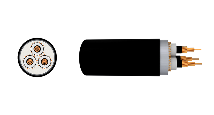
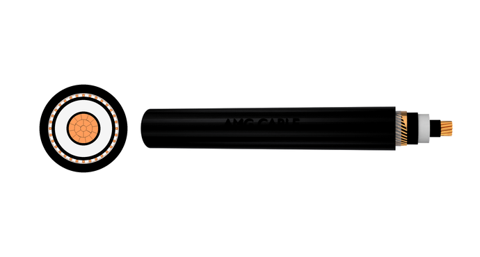
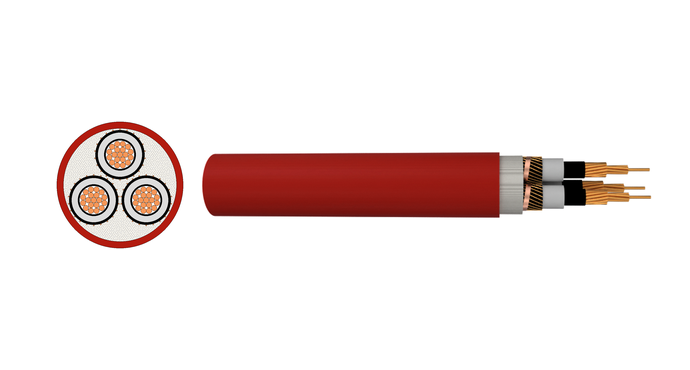
Get A Free Quote
Need Help?
Your Trusted Business Partner for Professional Cable Solutions
/ AMG FAQ /
Frequently Asked Questions
Published by the International Electrotechnical Commission, IEC 60502 is a family of standards that covers the construction, dimensions and test requirements for power cables with extruded solid insulation and their accessories.It covers rated AC voltages from 1 kV (Um = 1,2 kV) up to 30 kV (Um = 36 kV), which is the range commonly used in utility distribution networks and industrial power systems. The complete series is organized into the following parts:
- IEC 60502-1: Covers low-voltage cables for rated voltages of 1 kV (Um = 1,2 kV) and 3 kV (Um = 3,6 kV).
- IEC 60502-2: Covers medium-voltage cables for rated voltages from 6 kV (Um = 7,2 kV) up to 30 kV (Um = 36 kV).
- Part 3: Reserved for future use.
- IEC 60502-4: Covers test requirements on accessories for cables with rated voltages from 6 kV (Um = 7,2 kV) up to 30 kV (Um = 36 kV).
The entire series falls under the general title *”Power cables with extruded insulation and their accessories for rated voltages from 1 kV (Um = 1,2 kV) up to 30 kV (Um = 36 kV)”.
The scope of the IEC 60502 series covers power cables and their associated accessories with rated AC voltages ranging from 1 kV up to 30 kV.
- Structural Design: It outlines requirements for conductors, insulation compounds (like XLPE or EPR), shielding, armoring, and outer sheathing.
- Environmental/Fire Performance: It sets guidelines for cables with reduced flame spread, low smoke emission, and halogen-free gas properties.
- Testing: It defines strict protocols for factory testing (routine and sample tests), type qualification tests, and tests required after the cables are installed in the field.
The IEC 60502-2 voltage test refers to a series of electrical tests designed to verify the insulation integrity of medium-voltage (MV) cables rated from 6 kV to 30 kV. The standard breaks testing down into four main categories:
- Routine Voltage Test (Factory): Performed on 100% of manufactured lengths. Every cable must withstand an AC power frequency voltage of 3.5 x U0 for 5 minutes without insulation breakdown (where U0 is the rated voltage to ground).
- Partial Discharge (PD) Test: A companion factory test that checks for microscopic air voids within the insulation. Discharge must not exceed 10 pC at 1.73 x U0.
- Sample Voltage Test (Batch): A destructive quality check performed on short production segments. The sample must withstand 4 x U0 continuously for 4 hours.
- After-Installation Test (Field): Conducted after deployment and splicing to catch mechanical damage. Technicians typically use a Very Low Frequency (VLF) AC test at 3 x U0 for 15 to 60 minutes, or run the cable at normal system voltage for 24 hours under no-load.
Additionally, a Sheath Integrity Test applies 10 kV DC for 1 minute to ensure the outer plastic jacket has no punctures.
The primary difference between IEC 60502-1 and IEC 60502-2 is their voltage rating and application scope:
- IEC 60502-1 applies to power cables with extruded solid insulation for rated AC voltages of 1 kV (1.2 kV) and 3 kV (3.6 kV), as used in low-voltage (LV) fixed installations.
- IEC 60502-2 applies to cables with extruded solid insulation for rated AC voltages from 6 kV (7.2 kV) up to 30 kV (36 kV), used in medium-voltage (MV) fixed installations.
This leads to further differences in technical and test requirements:
- Insulation Thickness: IEC 60502-2 specifies considerably thicker and more robust insulation due to the higher operating voltage of medium-voltage cables.
- Screening: In contrast to IEC 60502-1, which covers simpler low-voltage constructions, IEC 60502-2 mandates the inclusion of conductor screens, insulation screens, and metallic screens for all cables to properly control the electric field.
- Water Ingress: A key concern for medium-voltage cables is water ingress. IEC 60502-2 includes specific provisions and associated tests for barriers to prevent longitudinal water penetration, a requirement not found in IEC 60502-1.
The latest edition of IEC 60502-2 is IEC 60502-2:2014+AMD1:2024 CSV, published on 2024-05-30.
This is Edition 3.1, a Consolidated Version (CSV) that merges the base 2014 standard (Edition 3.0) with its 2024 amendment (AMD1:2024) into one complete, ready-to-use document. Key technical updates in this version include a simplified calculation for lead sheath and oversheath thickness, a new method for determining cable conductor temperature, a modified routine voltage test procedure, a new routine electrical test on the oversheath, modified requirements for non-metal sheaths, and the addition of a 0.1 Hz test after installation. Specifying this latest CSV demonstrates that your cable designs are aligned with the most current international safety and performance requirements.

Have Questions?
Get in Touch with Us.
AMG Cable Group support 24*7 service and technical assistance.
Phone /Whatsapp / Wechat
+86 188 3803 6118Address
High-Tech Industrial Development Zone,Zhengzhou City,Henan Province,ChinaSend Us a Message
Please feel free to leave a message. We will reply in 24 hours.
/ AMG WIRE&CABLE /
Your trusted partner in high- performance wire and cables
Our team stands by 24/7, responding promptly to
inquiries and providing most quotations within 24 hours.