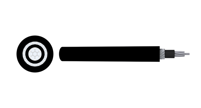
Product Description
CCS(30% Conductivity)is designed for use as grounding conductors in primary surge arrester systems.
Application
Ideal for grounding in electrical systems, particularly for primary surge arresters.
Applicable Standard
ASTM B228 ,ASTM B910
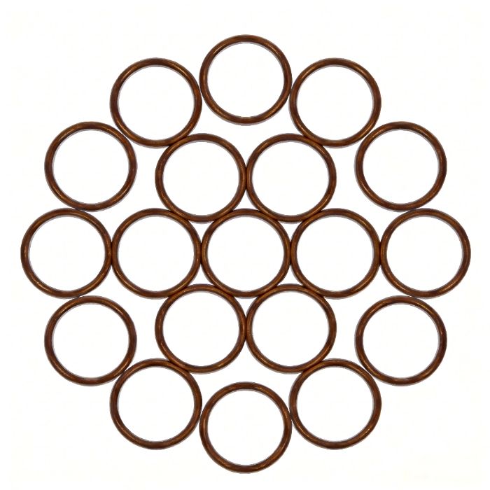
Construction
Technical Parameters
| Conductor | Conductor Size AWG |
Overall Dia | Min.Breaking Loads |
Weight | Cross Section Area |
I2t | Approx.Short- time Fusing Current at 30 Cycles (kA) |
Nominal DC Resistance at 68°F (Ω/KFT) |
|||||
| Wire No. |
AWG | inch | mm | Ibf | kN | Ibs/kft | kg/km | cmil | mm2 | kA2s | |||
| 1 | 2 | No.2 | 0.258 | 6.54 | 2276 | 10.10 | 184.1 | 274.04 | 66368 | 33.63 | 30.26 | 7.78 | 0.5209 |
| 1 | 4 | No.4 | 0.204 | 5.19 | 1431 | 6.40 | 115.8 | 172.34 | 41738 | 21.15 | 11.97 | 4.89 | 0.8283 |
| 1 | 6 | No.6 | 0.162 | 4.12 | 900 | 4.00 | 72.8 | 108.39 | 26250 | 13.30 | 4.73 | 3.08 | 1.3169 |
| 3 | 4 | 3 No.4 | 0.440 | 11.18 | 4079 | 18.10 | 350.2 | 521.17 | 125215 | 63.45 | 107.73 | 14.68 | 0.2761 |
| 3 | 5 | 3 No.5 | 0.392 | 9.96 | 3234 | 14.40 | 277.6 | 413.15 | 99263 | 50.30 | 6770 | 11.64 | 0.3483 |
| 3 | 6 | 3 No.6 | 0.349 | 8.87 | 2565 | 11.40 | 220.2 | 327.70 | 78732 | 39.89 | 42.59 | 9.23 | 0.4391 |
| 3 | 7 | 3 No.7 | 0.311 | 790 | 2035 | 9.10 | 174.7 | 260.00 | 62467 | 3165 | 26.81 | 732 | 0.5534 |
| 3 | 8 | 3 No.8 | 0.277 | 7.03 | 1614 | 720 | 138.5 | 206.18 | 49537 | 25.10 | 16.86 | 5.81 | 0.6979 |
| 3 | 9 | 3 No.9 | 0.247 | 6.26 | 1279 | 5.70 | 109.8 | 163.42 | 39262 | 19.89 | 10.59 | 4.60 | 0.8805 |
| 3 | 10 | 3 No.10 | 0.220 | 5.58 | 1015 | 4.50 | 87.1 | 129.66 | 31151 | 15.78 | 6.67 | 3.65 | 1.1098 |
| 3 | 12 | 3 No.12 | 0.174 | 4.42 | 638 | 2.80 | 54.8 | 81.52 | 19586 | 9.92 | 2.64 | 2.30 | 1.7650 |
| 7 | 4 | 7 No.4 | 0.613 | 15.57 | 9017 | 40.10 | 818.8 | 1218.48 | 292169 | 148.04 | 586.53 | 34.25 | 0.1183 |
| 7 | 5 | 7 No.5 | 0.546 | 13.86 | 7148 | 31.80 | 649.1 | 965.93 | 231613 | 11736 | 368.59 | 2715 | 0.1493 |
| 7 | 6 | 7 No.6 | 0.486 | 12.34 | 5670 | 25.20 | 514.8 | 766.15 | 183708 | 93.09 | 231.89 | 21.54 | 0.1882 |
| 7 | 7 | 7 No.7 | 0.433 | 11.00 | 4498 | 20.00 | 408.5 | 60787 | 145757 | 73.86 | 145.98 | 17.09 | 0.2372 |
| 7 | 8 | 7 No.8 | 0.386 | 9.79 | 3567 | 15.90 | 323.9 | 482.04 | 115586 | 58.57 | 91.80 | 13.55 | 0.2991 |
| 7 | 9 | 7 No.9 | 0.343 | 8.72 | 2827 | 12.60 | 256.7 | 382.06 | 91612 | 46.42 | 5767 | 10.74 | 0.3774 |
| 7 | 10 | 7 No.10 | 0.306 | 776 | 2243 | 10.00 | 203.7 | 303.13 | 72685 | 36.83 | 36.30 | 8.52 | 0.4756 |
| 19 | 5 | 19 No.5 | 0.910 | 23.10 | 19402 | 86.30 | 1768.7 | 2632.20 | 628665 | 318.55 | 2715.55 | 73.70 | 0.0550 |
| 19 | 6 | 19 No.6 | 0.810 | 20.57 | 15389 | 68.50 | 1402.9 | 208777 | 498636 | 252.66 | 1708.39 | 58.45 | 0.0693 |
| 19 | 7 | 19 No.7 | 0.722 | 18.33 | 12210 | 54.30 | 1113.1 | 1656.48 | 395627 | 200.47 | 1075.46 | 46.38 | 0.0874 |
| 19 | 8 | 19 No.8 | 0.643 | 16.32 | 9682 | 43.10 | 882.7 | 1313.59 | 313733 | 158.97 | 676.30 | 36.78 | 0.1102 |
| 19 | 9 | 19 No.9 | 0.572 | 14.53 | 7674 | 34.10 | 699.6 | 1041.13 | 248660 | 126.00 | 424.85 | 29.15 | 0.1390 |
| Conductor | Conductor Size AWG |
OverallDia. | Min.Breaking Loads |
Weight | Cross Section Area |
I2t | Approx.Short- time Fusing Current at 30 Cycles (kA) |
Nominal DC Resistance at 68°F (Ω/KFT) |
|||||
| Wire No. |
AWG | inch | mm | Ibf | kN | Ibs/kft | kg/km | cmil | mm2 | kA2s | |||
| 1 | 2 | No.2 | 0.258 | 6.54 | 2023 | 9.0 | 186.1 | 276.94 | 66368 | 33.63 | 40.29 | 8.98 | 0.3907 |
| 1 | 4 | No.4 | 0.204 | 5.19 | 1272 | 5.7 | 1170 | 174.16 | 41738 | 21.15 | 15.94 | 5.65 | 0.6212 |
| 1 | 6 | No.6 | 0.162 | 4.12 | 800 | 3.6 | 73.6 | 109.54 | 26250 | 13.3 | 6.30 | 3.55 | 0.9877 |
| 3 | 4 | 3 No.4 | 0.44 | 11.18 | 3626 | 16.1 | 353.9 | 526.67 | 125215 | 63.45 | 143.43 | 16.94 | 0.2087 |
| 3 | 5 | 3 No.5 | 0.392 | 9.96 | 2874 | 12.8 | 280.5 | 417.51 | 99263 | 50.3 | 90.13 | 13.43 | 0.2633 |
| 3 | 6 | 3 No.6 | 0.349 | 8.87 | 2280 | 10.1 | 222.5 | 331.16 | 78732 | 39.89 | 56.70 | 10.65 | 0.3319 |
| 3 | 7 | 3 No.7 | 0.311 | 790 | 1809 | 8.0 | 176.6 | 262.75 | 62467 | 31.65 | 35.70 | 8.45 | 0.4184 |
| 3 | 8 | 3 No.8 | 0.277 | 703 | 1434 | 6.4 | 140.0 | 208.36 | 49537 | 25.1 | 22.45 | 6.70 | 0.5276 |
| 3 | 9 | 3 No.9 | 0.247 | 6.26 | 1137 | 5.1 | 111.0 | 165.14 | 39262 | 19.89 | 14.10 | 5.31 | 0.6657 |
| 3 | 10 | 3 No.10 | 0.22 | 5.58 | 902 | 4.0 | 88.0 | 131.02 | 31151 | 15.78 | 8.88 | 4.21 | 0.8390 |
| 3 | 12 | 3 No.12 | 0.174 | 4.42 | 567 | 2.5 | 55.4 | 82.38 | 19586 | 9.92 | 3.51 | 2.65 | 1.3344 |
| 7 | 4 | 7 No.4 | 0.613 | 15.57 | 8015 | 35.7 | 827.4 | 1231.34 | 292169 | 148.04 | 780.87 | 39.52 | 0.0896 |
| 7 | 5 | 7 No.5 | 0.546 | 13.86 | 6354 | 28.3 | 655.9 | 976.13 | 231613 | 11736 | 490.72 | 31.33 | 0.1131 |
| 7 | 6 | 7 No.6 | 0.486 | 12.34 | 5040 | 22.4 | 520.2 | 774.23 | 183708 | 93.09 | 308.72 | 24.85 | 0.1425 |
| 7 | 7 | 7 No.7 | 0.433 | 11.00 | 3998 | 178 | 412.8 | 614.29 | 145757 | 73.86 | 194.34 | 19.72 | 0.1797 |
| 7 | 8 | 7 No.8 | 0.386 | 9.79 | 3171 | 14.1 | 3273 | 48713 | 115586 | 58.57 | 122.21 | 15.63 | 0.2266 |
| 7 | 9 | 7 No.9 | 0.343 | 8.72 | 2513 | 11.2 | 259.4 | 386.09 | 91612 | 46.42 | 76.77 | 12.39 | 0.2858 |
| 7 | 10 | 7 No.10 | 0.306 | 776 | 1994 | 8.9 | 205.8 | 306.33 | 72685 | 36.83 | 48.33 | 9.83 | 0.3603 |
| 19 | 5 | 19 No.5 | 0.91 | 23.10 | 17246 | 76.7 | 17874 | 2659.98 | 628665 | 318.55 | 3615.33 | 85.03 | 0.0418 |
| 19 | 6 | 19 No.6 | 0.81 | 20.57 | 13679 | 60.8 | 1417.7 | 2109.81 | 498636 | 252.66 | 2274.45 | 6745 | 0.0527 |
| 19 | 7 | 19 No.7 | 0.722 | 18.33 | 10853 | 48.3 | 1124.8 | 1673.96 | 395627 | 200.47 | 143180 | 53.51 | 0.0665 |
| 19 | 8 | 19 No.8 | 0.643 | 16.32 | 8606 | 38.3 | 892.0 | 132745 | 313733 | 158.97 | 900.39 | 42.44 | 0.0838 |
| 19 | 9 | 19 No.9 | 0.572 | 14.53 | 6821 | 30.3 | 7070 | 1052.12 | 248660 | 126 | 565.62 | 33.63 | 0.1057 |
| 19 | 0.528 | 13.40 | 5801 | 25.8 | 601.2 | 894.78 | 211475 | 10716 | 409.10 | 28.60 | 0.1243 | ||
| 19 | 10 | 19 No.10 | 0.51 | 12.94 | 5412 | 24.1 | 560.9 | 834.76 | 197289 | 99.97 | 356.05 | 26.69 | 0.1333 |
| 7 | 2/00 | 0.414 | 10.51 | 3652 | 16.2 | 3770 | 561.01 | 133115 | 6745 | 162.09 | 18.01 | 0.1967 | |
FAQs
A CCS (Copper Clad Steel) conductor is a high-performance, bimetallic conductor designed for applications where both electrical efficiency and mechanical durability are essential. It consists of a high-strength steel core that is thinly coated with a layer of copper. This unique construction combines the high mechanical resistance of steel with the excellent conductivity and corrosion resistance of copper.
CCS conductors are manufactured in a concentric-lay-stranded construction. The steel core provides mechanical strength that is roughly double that of pure copper. They are available in various conductivity grades, such as 20%, 30%, or 40% IACS.
The full form of CCS conductor is Copper Clad Steel Conductor. It is also commonly called copper-coated steel conductor or copper-covered steel wire. The conductor consists of a steel core surrounded by a continuous copper layer, which provides improved conductivity and corrosion protection compared with bare steel wire.
The main difference between CCA and CCS cable is the core material. CCA (Copper Clad Aluminum) uses an aluminum core with a copper coating, making it lightweight and cost-effective. CCS (Copper Clad Steel) uses a steel core with a copper coating, providing much higher tensile strength and mechanical durability. CCA is mainly used for lightweight signal and communication applications, while CCS is preferred for grounding, antenna, and applications requiring higher strength.
CCS conductor is not better than pure copper in terms of electrical conductivity. Pure copper provides higher conductivity and better current-carrying performance. However, CCS conductor has advantages in mechanical strength, durability, and cost efficiency. The steel core allows CCS conductors to withstand higher pulling forces and mechanical stress, making them suitable for applications where strength is more important than maximum conductivity.
CCS conductors are renowned for their exceptional longevity. They have maintained a century-long reputation for durability.
General lifespan: Many sources state a service life of more than 30 years.
Buried applications: For buried grounding conductors, CCS can be expected to have a 50+ year service life.
Field-proven: Copperweld CCS grounding conductors, now known as Copperweld Century™, have over 100 years of service in the field. This long life is due to its superior resistance to fatigue and corrosion.
Due to its unique combination of strength and conductivity, CCS is used in a wide variety of applications across different industries.
Grounding Systems: It is a primary choice for grounding in utility, industrial, and electric rail applications. This includes substation grounding grids, utility pole grounds, fence grounds, transformer and switch gear grounding, structure grounding, and lightning protection.
Cable TV and Data Transmission: It is widely used as the inner conductor in coaxial cables for CATV, CCTV, and radio antenna installations due to the “skin effect,” where signals travel on the outer copper surface.
Other Uses: It is also used in computer LAN, access network cables, telephone drop-wire, and as a messenger wire.
Yes, CCS cable can be a good choice for specific applications where high strength, corrosion resistance, and cost control are important. Compared with pure copper cable, CCS cable is stronger and often more economical. However, it has lower electrical conductivity than pure copper, so it is not suitable for applications requiring maximum current-carrying capacity. The right choice depends on the project requirements and operating conditions.
Yes, CCS conductor can be soldered because its outer layer is copper. However, proper soldering methods and surface preparation are required to ensure a reliable connection. The copper coating thickness, soldering temperature, and application conditions should be considered. For critical installations, suitable connectors or mechanical bonding methods may provide better long-term reliability.