

Medium Voltage Cable
Medium Voltage (MV) power cables serve as the critical infrastructure links engineered to distribute electrical energy safely and reliably within a voltage range typically spanning from 1kV up to 35kV. They act as the essential bridge between high-voltage bulk transmission grids and low-voltage end-use distribution systems, handling continuous, intense electrical stress.
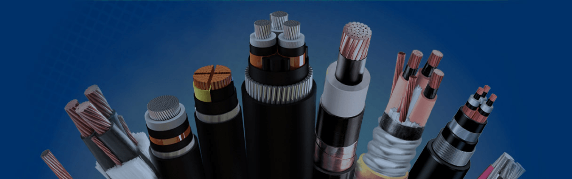
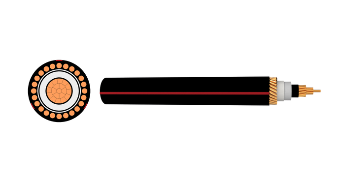
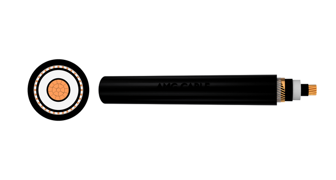
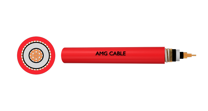
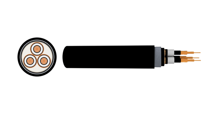
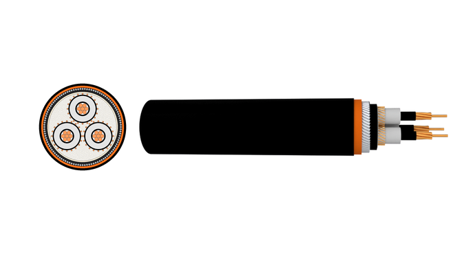
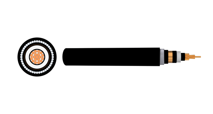
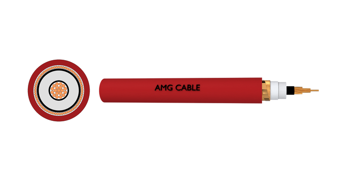
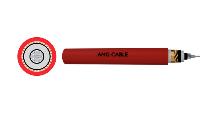
To withstand continuous electrical stress over decades, the main construction of an MV cable relies on a precise, multi-layer design. At the core is a copper or aluminum conductor, which is immediately covered by an extruded semi-conductive conductor shield to smooth out electrical fields. Next, the primary insulation layer acts as the main barrier against breakdown; industry standards include XLPE for general industrial power, Tree-Retardant XLPE (TR-XLPE) to prevent moisture-induced “water treeing” in direct-burial lines, and EPR rubber for enhanced flexibility and thermal cycling resistance.
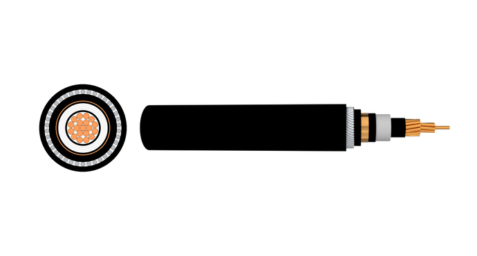
Directly over the insulation, a semi-conductive shield and a metallic screen (copper tape or wires) confine the electrical field, ground fault currents, and block electromagnetic interference. For harsh environments, mechanical protection like Steel Tape Armor (STA) for crushing defense or Steel Wire Armor (SWA) for high tensile strength is added, all enclosed in a durable PVC, PE, or fire-safe LSZH outer jacket.
When sourcing North American standard cables, you will encounter MV-90 and MV-105 thermal ratings, which specify the maximum continuous conductor temperature. Standard MV-90 cables are rated for 90°C and suit most traditional circuits, while MV-105 cables handle up to 105°C, offering higher current-carrying capacity and an extra safety margin for high-heat or emergency overload conditions.
Medium Voltage Cable Classification & Technical Comparison
| Type | Common Voltage Ratings | Conductor & Insulation Types | Sheath & Armor Options | Insulation & Shielding | Typical Applications |
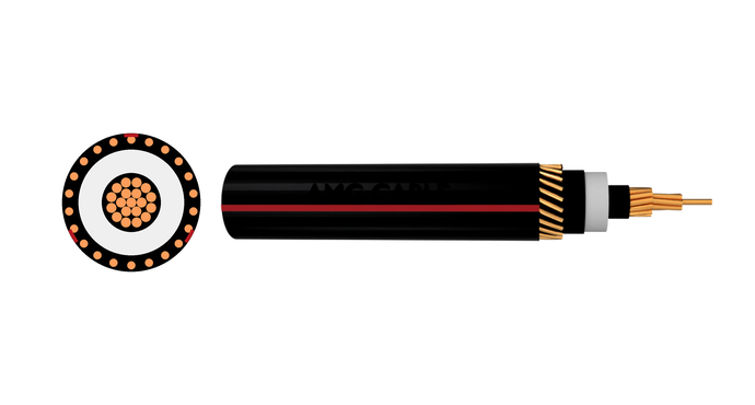
| URD Medium Voltage Cable | 15kV, 25kV, 35kV | Aluminum or copper conductor with TR-XLPE insulation | PE sheath, unarmored | Concentric neutral or copper wire shield | Underground residential distribution systems |
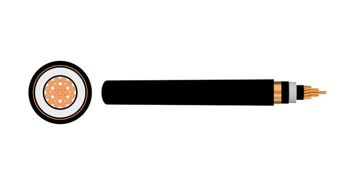
| Type MV Power Cable | 5kV–35kV | Copper or aluminum conductor with XLPE or EPR insulation | PVC, PE, or LSZH sheath | Copper tape shield or copper wire shield | Industrial and utility power distribution |
| Type SH Cable | 5kV–15kV | Flexible copper conductor with EPR insulation | Heavy-duty rubber sheath | Shielded flexible construction | Mining equipment and portable power systems |
| Armored Medium Voltage Cable | 6/10kV, 12/20kV, 18/30kV | Copper or aluminum conductor with XLPE insulation | Steel tape armor (STA) or steel wire armor (SWA) | Copper wire screened | Direct burial and mechanically demanding installations |
| LSZH Medium Voltage Cable | 6kV–35kV | Copper or aluminum conductor with XLPE insulation | Low smoke zero halogen sheath | Copper tape or wire shield | Commercial buildings, tunnels, airports, and public infrastructure |
| Single Core MV Cable | 6kV–35kV | Copper or aluminum conductor with XLPE insulation | PVC, PE, or LSZH sheath | Copper wire screen | High-current transmission and substations |
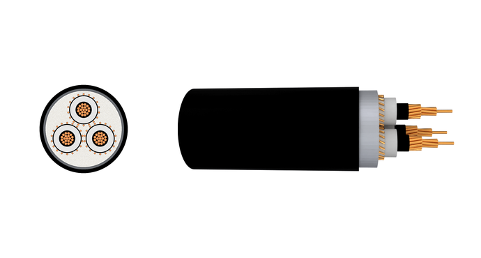
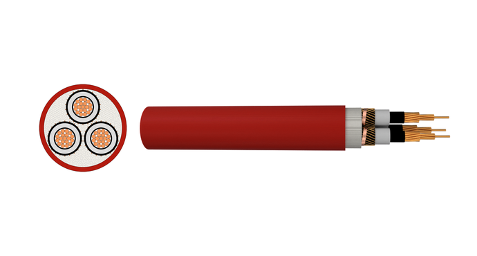
| Three Core MV Cable | 6kV–35kV | Copper or aluminum conductor with XLPE insulation | Armored or unarmored structure | Individual or overall screen | Three-phase distribution systems |
| Mining Medium Voltage Cable | 5kV–15kV | Flexible copper conductor with EPR insulation | Abrasion-resistant rubber sheath | Reinforced shielding system | Mining operations and mobile industrial equipment |
Medium Voltage Cable Standards
| Standard | Region | What It Covers |
| IEC 60502-2 | International | Extruded XLPE-insulated power cables for rated voltages 6 kV up to 30 kV. Covers construction, routine tests, and permissible continuous operating temperatures. |
| BS 6622 | United Kingdom | Armoured MV cables with XLPE insulation and PVC outer sheath. Includes requirements for armouring wires, bedding, and electrical testing. |
| BS 7835 | United Kingdom | Same construction requirements as BS 6622, but specifies a low-smoke zero-halogen (LSZH) outer sheath for installations where fire safety and low smoke are critical. |
| AS/NZS 1429.1 | Australia / New Zealand | MV cables with extruded insulation for 1.9/3.3 kV up to 19/33 kV. Covers single-core, three-core individually screened, and triplex constructions. |
| UL 1072 | North America | Medium voltage power cables from 5 kV to 35 kV. Defines temperature ratings MV-90 and MV-105, insulation materials, and the VW-1 flame test. |
| ICEA S-94-649 | North America | Concentric neutral underground residential distribution (URD) cables, requiring tree-retardant XLPE (TR-XLP) insulation for direct-burial service. |
| VDE 0276 | Germany / Europe | German standard for MV cables with extruded insulation, closely aligned with IEC 60502-2. Often required for utility and industrial projects in Central Europe. |
| VDE 0250 / DIN VDE | Germany | Covers heavy-duty reeling and trailing cables, including those for mobile mining equipment, with reinforced sheaths and flexible conductors. |
Medium Voltage Cable
Get A Free Quote
Need Help?
Your Trusted Business Partner for Professional Cable Solutions
/ AMG FAQ /
Frequently Asked Questions
Sizing a medium voltage cable involves more than picking a cross-section that matches the load current. You need to determine the minimum conductor size based on the expected continuous current (ampacity), accounting for installation conditions such as ambient temperature, soil thermal resistivity, and grouping with other cables. Then you verify the selection under short-circuit conditions to ensure the conductor and metallic screen can handle the fault current for the required clearing time without exceeding their thermal limits. Voltage drop over the intended cable run must also stay within the limits set by the project or local code. Finally, the chosen size must meet the minimum cross-section required by the applicable standard (for example, IEC 60502-2 or UL 1072) for the voltage rating. A reliable sizing exercise looks at ampacity, short-circuit rating, voltage drop, and standard minimums — not just the load amps.
Best practices cover both factory tests and field tests. At the factory, routine tests should include a partial discharge test, a high-voltage AC test, and a conductor resistance check on every manufactured length. Sample tests on finished cables typically cover tensile strength, elongation, and hot set for the insulation and jacket. In the field, after installation and before energization, a DC high-potential test or a very low frequency (VLF) AC test is performed to verify the integrity of the installed cable system. VLF testing at 0.1 Hz is now preferred over DC for service-aged XLPE cables because DC can cause space charge accumulation that may lead to premature failure. A sheath integrity test is also important, especially for cables with a metallic moisture barrier. Finally, testing terminations and joints with the same care as the cable itself is essential — many issues show up at accessories first.
Medium voltage cables act as the essential distribution backbone of modern electrical
infrastructure, operating where low-voltage cables (under 1 kVcannot efficiently carry high
power loads and high-voltage transmission lines (above 35 kV to 669 kV) are too bulky or
dangerous to install. Their primary applications include:
Utility Substation & Grid Distribution: Interconnecting heavy step-down transformers inside electrical substations and feeding power out to municipal underground residential distribution (URD) networks or overhead distribution lines.
Industrial Manufacturing & Processing Plants: Supplying primary bulk power to massive electrical loads in heavy industries such as steel mills, paper factories, automobile assembly plants, and chemical manufacturing facilities.
Renewable Energy Generation: Serving as collection cables within large-scale wind farms and solar photovoltaic arrays. They collect medium-voltage power from individual wind turbine generators or solar inverters and route it across the site to a centralized step-up substation.
Oil, Gas, and Petrochemical Infrastructure: Routing power through refineries, offshore drilling platforms, and pumping stations. These environments frequently mandate specialized Lead Sheathed MV Cables to prevent corrosive chemical and hydrocarbon ingress.
Transportation & Infrastructure Hubs: Powering critical, high-availability facilities like commercial airports, seaports, and electric rail or subway traction power systems where continuous downtime would cause widespread disruption.
Mining Operations: Providing power to heavy mobile machinery, draglines, and shovels in both underground and open-pit mines. These operations rely on highly flexible, rugged rubber-jacketed cables (such as Type SH or German standard N3GHSSYCY).
Medium voltage cables are shielded because the electric field strength at these voltages is high enough that it must be contained and controlled. An unshielded MV cable would create a strong electric field in the air around the cable, which can stress adjacent insulation, induce voltages on nearby metallic objects, and cause corona or surface tracking at the jacket. The metallic shield — whether copper tape or copper wires — performs two essential jobs: it creates a smooth, grounded equipotential surface that confines the electric field entirely inside the cable, and it provides a predictable, low-impedance path for short-circuit and capacitive charging currents. Without a proper shield, the cable’s outer surface could become a safety hazard and the cable would be susceptible to surface discharge, especially if the jacket becomes damp or contaminated.
The metallic shield or concentric neutral of a medium voltage cable must be grounded, but whether a separate, dedicated ground wire is required depends on the installation and local code. In many configurations, the copper tape or wire shield serves as the ground path and is bonded to the grounding system at one or both ends. If the shield cross-section does not meet the code requirement for an equipment grounding conductor for the circuit, then a separate ground wire may need to be included in the same duct, tray, or trench. Some designs use the concentric neutral as both neutral and ground. The key is ensuring that under a line-to-ground fault, the fault current has a low-impedance return path capable of clearing the upstream protection, and that touch potentials are kept safe. Always check the project’s earthing or grounding design and the relevant standard.
Typical direct-burial depths for medium voltage cables range from 24 inches (600 mm) to 36 inches (900 mm), but the exact depth is dictated by the applicable national code or utility standard. In North America, the National Electrical Code (NEC) often requires 30 to 36 inches for MV cables depending on voltage and location (e.g., under roads or not). In IEC-based systems, 600 to 800 mm is common for cables in open ground. Deeper burial may be required when crossing roadways or railways, while shallower depths can sometimes be used if the cable is installed in a duct bank or covered with a concrete slab. Always confirm with the local authority or the utility’s standard practice, and consider adding warning tape 12 inches above the cable to reduce the chance of dig-ins.
Yes, you can run medium voltage cables in cable trays, provided the cables are specifically rated and marked for tray use, and the installation adheres to standard electrical codes (such as NEC Article 392). This is a standard installation method inside industrial manufacturing complexes, chemical refineries, and power generation plants.
Key rules for installing MV cables in trays include:
Type MV Cable Certification: The cable jacket must be explicitly stamped with “Type MV” and certified as flame-retardant and sunlight-resistant (UV stabilized) to ensure it can safely handle exposed open-air routing in elevated trays.
Ventilated Trough or Ladder Trays Only: Solid-bottom trays are generally prohibited for high-power MV runs. Installations must utilize open ladder trays or ventilated trough trays to allow ambient air to circulate freely around the lines, preventing excessive heat build-up and maximizing the cable’s current carrying capacity (ampacity).
Single-Layer Placement & Spacing: To prevent mutual heating, medium voltage cables should generally be laid out in a single layer with distinct spacing between lines (typically maintaining a distance equal to at least one cable diameter), rather than being bunched or stacked haphazardly.
Clear Voltage Separation: MV cables cannot be mixed freely with low-voltage power lines or sensitive low-voltage control signaling wires in the same tray partition. They must be isolated using solid, grounded metal barriers, or installed in an entirely separate, dedicated MV cable tray system to eliminate the risk of high-voltage induction or flashover.
The most common failure locations on a medium voltage cable system are at terminations and splices (joints). These are the points where the factory-built insulation system is interrupted and reassembled by hand in the field, often under less-than-ideal conditions. Poor workmanship, contamination during jointing, incorrect application of stress cones, or insufficient insulation thickness at the splice can create high-stress points that develop into partial discharge and eventual breakdown. After accessories, the next most common failure sites are locations where the cable has been physically damaged — typically during installation or by third-party digging later. In cables that are not physically damaged, insulation degradation from water trees (in older non-TR-XLP XLPE) or thermal aging can lead to failures at random points along the route, often where the cable is in persistently wet soil. Keeping terminations clean and dry, training jointers well, and protecting the route are the best defenses.

Have Questions?
Get in Touch with Us.
AMG Cable Group support 24*7 service and technical assistance.
Phone /Whatsapp / Wechat
+86 188 3803 6118Address
High-Tech Industrial Development Zone,Zhengzhou City,Henan Province,ChinaSend Us a Message
Please feel free to leave a message. We will reply in 24 hours.
/ AMG WIRE&CABLE /
Your trusted partner in high- performance wire and cables
Our team stands by 24/7, responding promptly to
inquiries and providing most quotations within 24 hours.