Product Description
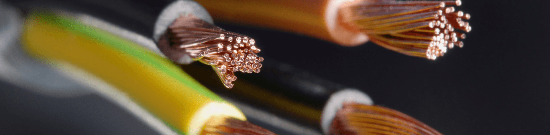
Welding cable, the electrical conductor for welding current, comprises fine copper strands (enhancing flexibility vs. other conductors) encased in a durable, non-conductive jacket—usually synthetic/natural rubber in various colors,resistant to repeated movement over rough surfaces. As amperage rises, the cables’ diameter and the cross-sectional area of its copper strands must increase.
Application
Welding cable, a durable, flexible secondary voltage-resistant cable for welding tools, generators, and industrial machinery, is ideal for demanding applications. Electric arc-welding tools typically use two: one as the primary power source, the other as the secondary (critical for the electrode). Beyond welding, it serves as cost-effective stage/entertainment lighting/sound cables, communication van wiring, car battery cables, inverter cables, and an alternative to pendant/reeling cables for hoists and cranes.
Applicable Standard
BS EN 50525-2-81,HD 22.6
Construction
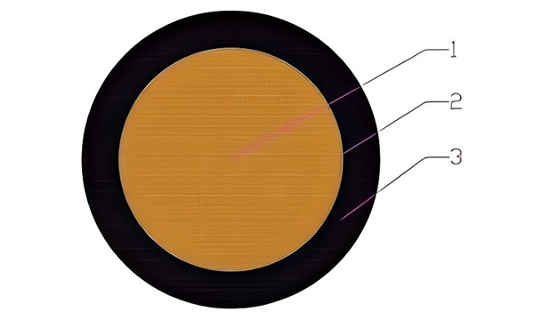
- 1. Conductor: Plain annealed copper wire
- 2. Binder tape: Polyester tape
- 3. Cover:Type EM 5 to EN 50363-2-2, the cover can consist of one or two layers(Black Color)
Technical Parameters
| Nominal Cross Section Area of Conductor |
Maximum Dia. of Wires in Conductor |
Thickness of Covering Specified Value |
Mean Overall Dia. | Max.Conductor Resistance at 20℃ |
||
| Lower Limit | Upper Limit | Untinned Wires |
Tinned Wires |
|||
| mm2 | mm | mm | mm | mm | Q/km | |
| H01N2-D | ||||||
| 10 | 0.21 | 2.0 | 7.7 | 9.7 | 191 | 1.95 |
| 16 | 0.21 | 2.0 | 8.8 | 11.0 | 1.21 | 1.24 |
| 25 | 0.21 | 2.0 | 10.1 | 12.7 | 0.780 | 0.795 |
| 35 | 0.21 | 2.0 | 11.4 | 14.2 | 0.554 | 0.565 |
| 50 | 0.21 | 2.2 | 13.2 | 16.5 | 0.386 | 0.393 |
| 70 | 0.21 | 2.4 | 15.3 | 19.2 | 0.272 | 0.277 |
| 95 | 0.21 | 2.6 | 17.1 | 21.4 | 0.206 | 0.210 |
| 120 | 0.51 | 2.8 | 19.2 | 24.0 | 0.161 | 0.164 |
| 150 | 0.51 | 3.0 | 21.1 | 26.4 | 0.129 | 0.132 |
| 185 | 0.51 | 3.2 | 23.1 | 28.9 | 0.106 | 0.108 |
| 240 | 0.51 | 3.4 | 25.8 | 32.1 | 0.0817 | 0.0801 |
| Nominal Cross Section Area of Conductor |
Maximum Dia. of Wires in Conductor |
Thickness of Covering Specified Value |
Mean Overall Dia. | Max.Conductor Resistance at 20℃ |
||
| Lower Limit | Upper Limit | Untinned Wires |
Tinned Wires |
|||
| mm2 | mm | mm | mm | mm | Q/km | |
| H01N2-E | ||||||
| 10 | 0.16 | 1.2 | 6.2 | 7.8 | 191 | 1.95 |
| 16 | 0.16 | 1.2 | 73 | 9.1 | 1.21 | 1.24 |
| 25 | 0.16 | 1.2 | 8.6 | 10.8 | 0.780 | 0.795 |
| 35 | 0.16 | 1.2 | 9.8 | 12.3 | 0.554 | 0.565 |
| 50 | 0.16 | 1.5 | 11.9 | 14.8 | 0.386 | 0.393 |
| 70 | 0.16 | 1.5 | 13.6 | 170 | 0.272 | 0.277 |
| 95 | 0.16 | 1.8 | 15.6 | 19.5 | 0.206 | 0.210 |
| 120 | 0.21 | 1.8 | 17.2 | 21.6 | 0.161 | 0.164 |
| 150 | 0.21 | 1.8 | 18.8 | 23.5 | 0.129 | 0.132 |
| 185 | 0.21 | 1.8 | 20.4 | 25.5 | 0.106 | 0.108 |
| 240 | 0.21 | 2.0 | 23.0 | 28.0 | 0.0817 | 0.0801 |